NeuralNexus Arm: a 6-DOF Arm Built from Scratch, from CAD to Digital Twin
📌 What this guide covers
This build breaks from the pattern of the other guides here: it is not a copy of an existing open-source arm. The mechanics, the firmware, the kinematics, the digital twin and the vision pipeline were all built from scratch — no kit, no off-the-shelf motion stack. The project has a single thesis: one command makes the physical arm and its 3D digital twin move together.
Because the authors (Lasan Perera and four co-authors) carried the whole chain through, it works extremely well as a textbook for what a robot arm is actually made of: SolidWorks CAD → Simscape Multibody digital twin → MATLAB inverse kinematics → USB CDC at 115200 → STM32H743 real-time servo loop → six steppers plus a servo gripper → AS5047P absolute encoder feedback.
The guide runs system chain → hardware stack → joint transmission → control & protocol → digital twin → vision → downloads → pitfalls. The value is not "build this exact machine" but learning how each layer interfaces and how to verify it.
🧭 Part 1: the system chain (understand the data flow first)
Hold this chain in mind and every later section snaps into place: the host solves the kinematics, sends joint angles over serial, and the MCU does the real-time servo work. A deliberately minimal text protocol decouples the two sides, so each can be developed and debugged alone.
SolidWorks CAD  ->  Simscape Multibody digital twin  ->  MATLAB inverse-kinematics solve
                                     |
                        USB CDC @ 115200 baud (joint-angle text protocol)
                                     v
        STM32H743 @ 420 MHz  ->  6 stepper motors + gripper servo (2 kHz control loop)
                                     |
                    AS5047P absolute encoders (SPI feedback, 14 bit)
                                     |
        Browser Web Serial control panel (Chrome / Edge, no MATLAB license needed)
- Geometry layer: SolidWorks bodies imported into Simscape Multibody as a rigid-body tree (
importrobot('Assem1')); link dimensions and joint limits are defined here. - Planning layer: MATLAB solves IK with the Robotics System Toolbox
inverseKinematicssolver, producing six joint angles. - Transport layer: six comma-separated angles plus newline over a USB CDC virtual COM port, 115200 8N1.
- Execution layer: the STM32H743 advances all six axes inside a TIM6 interrupt at 2 kHz; the gripper runs on 50 Hz PWM.
- Feedback layer: six AS5047P magnetic encoders read over SPI1 (mode 1, 14 bit) for verification and future closed-loop work.
- Alternative entry point: no MATLAB install? The project ships a browser control panel that talks to the serial port directly via the Web Serial API.
🔧 Part 2: the hardware stack (selection logic beats part numbers)
| Item | Configuration |
|---|---|
| MCU | STM32H743VITx (Cortex-M7 @ 420 MHz, 25 MHz HSE → PLL: M=5 / N=168 / P=2) |
| Steppers | 2 × NEMA 24 (J2 / J3) · 1 × NEMA 23 (J1) · 3 × NEMA 17 (J4 / J5 / J6) |
| Drivers | 2 × CL57T closed-loop (J2 / J3) · 1 × DM542 open-loop (J1) · 3 × onboard TMC2209 at 1/8 microstep (J4 / J5 / J6) |
| Encoders | 6 × AS5047P magnetic absolute encoders, 14 bit (16384 counts/rev), SPI1 mode 1 |
| Gripper | Hobby servo · TIM1_CH3 · 50 Hz PWM (930 µs open / 1100 µs close) |
| Peripheral map | TIM1_CH3 gripper · TIM2_CH2 buzzer · TIM6 stepper ISR @ 2 kHz · USB CDC virtual COM |
| Control loop | TIM6 ISR @ 2 kHz (PSC 74 / ARR 499), 500 µs tick |
| Wiring topology | M1–M3 common-anode (STEP+/DIR+/ENA+ to external +5 V, STM32 sinks via open-drain) · M4–M6 push-pull 3.3 V direct |
OUTPUT_PP, 3.3 V direct); the external CL57T / DM542s are open-drain (OUTPUT_OD, common-anode, active low). That is why Stepper_SetEnableM4M5M6(false) is in fact the call that enables the external drivers. It looks like a bug during code review — it is not. Think through the polarity before you "fix" it.⚙️ Part 3: joints, gearing and pulse scaling
| Joint | Role / motor / ratio / pulses per joint rev |
|---|---|
| J1 | Base rotation · NEMA 23 (DM542) · 1:7 · 2800 |
| J2 | Shoulder · NEMA 24 (CL57T closed-loop) · 1:30 · 5000 |
| J3 | Elbow · NEMA 24 (CL57T closed-loop) · 1:30 · 5000 |
| J4 | Wrist pitch · NEMA 17 (TMC2209 1/8) · 1:1 · design 1600 |
| J5 | Wrist roll · NEMA 17 (TMC2209 1/8) · 1:1 · design 1600 |
| J6 | Tool rotation · NEMA 17 (TMC2209 1/8) · 1:1 · design 1600, measured 3200 |
| Joint limits | J1 ±180° · J2 −70°…70° · J3 120°…240° · J4 ±180° · J5 60°…300° · J6 ±180° |
| Index mapping | jointToMotor[6] — logical joint numbering is not motor wiring order; the map lives in firmware and must be updated whenever wiring changes |
pulsesPerJointRev wrong and every angle scales wrong, which is exactly why absolute positioning currently works only on the 1:1 wrist joints.🖥️ Part 4: the serial protocol and control options
| Command | Format and meaning |
|---|---|
| Move joints | Six comma-separated angles in degrees → 0,-50,60,-80,-90,50; firmware converts to steps and echoes steps: ... |
| Gripper | G,1 close / G,0 open (TIM1_CH3 servo PWM) |
| Homing | HOME — encoder zero calibration |
| Self test | TEST — 30° encoder calibration routine |
| Operating mode | Relative mode: every command is a delta from the current pose. Absolute positioning and the J3/J5 180° offsets are implemented but disabled until encoder homing is finished. |
On the host side you have two options: a MATLAB session (solve IK, drive the twin, send angles) or the browser control panel (open the HTML in Chrome / Edge, click Connect, pick the COM port — no MATLAB license required). The standard MATLAB opening sequence is below; the very first step must create jointData, because the Simscape From Workspace blocks depend on it:
% Run this block at the start of every MATLAB session
jointData = zeros(2,7);            % must exist before loading the model
load_system('Assem1');
robot = importrobot('Assem1');
robot.DataFormat = 'row';
limitsDeg = [-180 180; -70 70; 120 240; -180 180; 60 300; -180 180];
for i = 1:6
    robot.Bodies{i}.Joint.PositionLimits = deg2rad(limitsDeg(i,:));
end
ik = inverseKinematics('RigidBodyTree', robot);
weights = [1 1 1 1 1 1];
q0 = homeConfiguration(robot);
s  = serialport("COM9", 115200);   % check Device Manager for the real port

% Typical actions
armIK(robot, ik, weights, q0)                         % interactive IK slider tool
goToXYZ(robot, ik, weights, q0, [-0.15 0.30 0.10], s) % XYZ to hardware + synced twin
moveBoth(s, [0 10 0 0 0 0])                           % move hardware and sim together
armWave(s)                                            % wave routine
writeline(s, "HOME")                                  % encoder homing
enc | ... print from firmware floods the port, so MATLAB's readline() == "END" waits forever and both the simulation and the hardware freeze. Pick one mode at a time, or add a timeout on the reading side.🧪 Part 5: the digital twin and the demos
The Simscape Multibody model in Mechanics Explorer is a full-size copy of the real arm. Every time MATLAB solves IK it writes joint angles into jointData, the From Workspace blocks read that two-column time table and drive the six revolute joints — press Run and the on-screen arm performs the same motion as the hardware on the bench.
- Position lock: the tip holds a fixed point in space while the tool orientation sweeps, showing how the links reconfigure around a locked end effector.
- Orientation lock + XYZ sweep: the tool angle is held while the tip sweeps along X, Y and Z in turn.
- Motion library: vertical square, wave and pick-and-place sequences are recorded (
drawSquare.m/armWave.m/objectPicking.mand friends). - Nullspace demo:
nullspaceDemo.mchanges the joint configuration at a fixed end-effector pose — a hands-on look at the arm's kinematic redundancy. - Scripted runs:
set_param('Assem1','SimulationCommand','start')starts the simulation from code, which is handy for batch checks.
👁️ Part 6: the vision pipeline (pixels → world coordinates → IK)
| Stage | Method and figures |
|---|---|
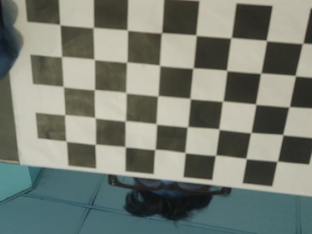
| Intrinsics | 20 chessboard images → reprojection error 0.6863 px (calibrate.py / calibrate picam.py) |
| Mounting | Camera rigidly fixed at 41 cm height; the extrinsics assume exactly that pose |
| Extrinsics | 3×3 homography mapping pixel coordinates to millimetre-scale world coordinates (homography.py) |
| Detection | Colour segmentation (segmentation.py) and YOLO detection with custom-trained models (cartons, candy, …) |
| Loop | Detection → world coordinates → inverse kinematics → joint angles → gripper action |
📥 Downloads (full official mirror, no VPN needed)
Everything below is a mirror of the original repository files, grouped by purpose and downloadable directly. Total: 248 files / about 27.7 MB.
docs · reports and presentations (EDR Documentation)
| File | Size | Notes |
|---|---|---|
| Neural_Nexus_Final_Report.pdf | 3.8 MB | Final technical report covering mechanics, electronics, firmware, kinematics and vision — start here |
| Neural_Nexus_Final_Presentation.pdf | 6.9 MB | Final presentation with photos, exploded views and result screenshots |
| Neural_Nexus_Project_Pitch.pdf | 0.4 MB | Project pitch: design goals and selection rationale |
schematics · electrical
| File | Size | Notes |
|---|---|---|
| MCU_Schematic.pdf | 0.3 MB | Main board: STM32H743 core, driver interfaces, power |
| Encoder_Schematic.pdf | 0.12 MB | AS5047P encoder board (SPI wiring, magnet placement) |
gerber · PCB fabrication files
| File | Size | Notes |
|---|---|---|
| MCU.rar | 0.24 MB | Main board Gerber package, ready to order |
| nema17.rar | 21 KB | NEMA 17 mount / adapter board |
| nema17pancake.rar | 20 KB | NEMA 17 pancake adapter board |
| nema23.rar | 22 KB | NEMA 23 (J1) mount |
| nema24.rar | 22 KB | NEMA 24 (J2 / J3) mounts |
eda · EasyEDA (LCEDA) Pro project (added by this site · editable source)
| File | Size | Notes |
|---|---|---|
| NeuralNexus_Arm.eprj2 | 1.3 MB | EasyEDA Pro (LCEDA) project package with one schematic (Schematic1 / P1) and one board (PCB1). Open it via File → Open → Local project to keep editing, then order straight from the fab |
| preview_schematic.webp · preview_pcb.webp | 23 KB / 112 KB | Built-in thumbnails of the schematic and the PCB — preview before downloading |
.eprj2 is the project format of EasyEDA Pro (LCEDA professional edition) — essentially a SQLite database; the standard edition cannot open it.⚠️ This project was created by this site and is not part of the official repository; it may differ from the official schematics, so use the files in
gerber/ for real fabrication.ik-matlab · MATLAB / Simscape project and models
| File | Size | Notes |
|---|---|---|
| GUIDE.txt | 6 KB | Command cheat sheet: session setup, IK solve, slider tool, hardware commands, demo order |
| REQUIREMENTS.txt | 0.6 KB | MATLAB release and toolbox requirements (Robotics System Toolbox, …) |
| Assem1.slx | 0.24 MB | Simscape Multibody digital twin with six revolute joints and From Workspace inputs |
| Assem1_DataFile.m | 10 KB | Auto-generated model parameters (link lengths, masses, inertias) |
| Part1–Part6.STL · endeff.STL | 0.9 MB total | Seven link / end-effector STL meshes for visualisation |
| Part1–Part6 / endeff · STEP | 0.58 MB total | Matching STEP solids for redesigns or format conversion (this site's online STL → STEP converter handles that class of model too) |
| armIK.m · goToXYZ.m · moveBoth.m | 1–2 KB each | Interactive IK tool, XYZ target dispatch, synced relative motion |
| drawSquare.m · armWave.m · objectPicking.m | 1–3 KB each | Motion library: vertical square, wave, pick-and-place |
| demoPositionLock.m · demoOrientationLock_XYZsweep.m | 1.5–1.7 KB | The two lock demos |
| nullspaceDemo.m · findDemoPoint.m | 1.4–1.8 KB | Redundancy demo and reachable-point search |
vision · scripts and calibration data
| File | Size | Notes |
|---|---|---|
| calibrate.py · calibrate picam.py | 5.6–6.2 KB | Chessboard intrinsic calibration (regular camera and Raspberry Pi camera) |
| homography.py | 3.7 KB | Homography solve: pixels → world coordinates |
| segmentation.py · detect_picam.py | 4.6–4.8 KB | Colour segmentation and the detection main loop (YOLO call included) |
| camera_matrix.npy · dist_coeffs.npy | 200 / 168 B | Calibration results: 3×3 intrinsics and distortion coefficients |
| candy.yaml | 183 B | Colour threshold parameters (candy example) |
| calib_photos/ (20 images) | 1.4 MB total | Chessboard photos so the calibration can be reproduced |
firmware · STM32H743 project (170 files / 11.8 MB)
| Path | Notes |
|---|---|
| REQUIREMENTS.txt | Build and hardware notes: toolchain, pin map, pulses per rev, the three USB CDC requirements, full serial protocol |
| Test1.0.ioc | STM32CubeMX configuration (clock tree, TIM6 at 2 kHz, USB CDC, SPI1, …) |
| Core/Src/main.c | Main program: stepper stepping, gripper PWM, protocol parsing, encoder reads |
| Core/Inc/main.h · stm32h7xx_it.c | Pin definitions and interrupt handlers |
| NeuralNexusArm1.0 Debug.launch | STM32CubeIDE flash / debug configuration — import and build straight away |
| STM32H743VITX_FLASH.ld · Drivers/ + Middlewares/ + USB_DEVICE/ | Linker script plus ST HAL / CMSIS / USB middleware, so the project builds without installing a separate firmware pack |
firmware/REQUIREMENTS.txt (one page for every assignment), then the stepping and protocol code in Core/Src/main.c, and finally cross-check with ik-matlab/GUIDE.txt to see how the host drives it.🚀 Part 7: quick start (three steps to a first motion)
- Firmware: import
firmware/into STM32CubeIDE (the.launchconfig is included) → build → flash via ST-Link → confirm the board enumerates as a USB virtual COM port. If you regenerate code from CubeMX, comment outMX_SDMMC1_SD_Init()again — with no SD card inserted it drops straight intoError_Handler()and the board hangs at boot. - Host: open
ik-matlab/in MATLAB and follow section 0 ofGUIDE.txt(jointData→importrobot→ joint limits → IK solver → serial), then rungoToXYZorarmIK. - No-MATLAB route: open the official control panel HTML in Chrome / Edge → Connect arm → choose the port → send angles directly. Run
clear sfirst to release the port from MATLAB, otherwise it will not open.
RCC_USBCLKSOURCE_HSI48); ② HAL_PWREx_EnableUSBVoltageDetector() is called before MX_USB_DEVICE_Init(); ③ you are on the board's native USB-C (PA11 / PA12) with a data-capable cable, not the ST-Link USB. If the COM number keeps changing, uninstall the greyed-out hidden entries in Device Manager and replug.🐛 Part 8: pitfalls (the section that saves the most time)
- The encoder "ghost drift" was a -1 sentinel. Failed reads returned
-1, those values went into a 30-sample average, and a stationary joint appeared to swing 60–70° — the sensor was always fine. Filter-1before averaging and repeatability returns to ±0.01°. The giveaway: it got worse at lower speed, whereas genuine signal-integrity problems always improve when you slow down. - Retiming an ISR can scale things wrong by 25×. Moving from 50 kHz to 2 kHz left
dt = 0.00002andstepInterval = 50000/speed, so every motor crawled. Correct values aredt = 0.0005andstepInterval = 2000/speed. - Home with raw motor indices.
Stepper_MoveAll()(nojointDir) is the correct call; using joint indices produces a two-way sign flip. - Send long moves in 10° chunks so nothing is interrupted, without touching the firmware.
- Telemetry or handshake, never both: periodic prints swallow the handshake packet.
- One mate pair per Simscape joint: any extra parallel or perpendicular mate locks the revolute joint.
- Moving the camera invalidates the extrinsics: the homography only holds for the calibrated pose; intrinsics survive.
- Measure pulses per rev per axis: J6 came out at 3200 instead of the designed 1600.
- Do not treat it as a product. The README states Status: Active Development and warns that bugs may exist; use is at your own risk.
📊 Current project status (per the authors)
| Subsystem | Status |
|---|---|
| 6-axis stepper control / USB CDC / joint mapping / direction signs | ✅ Done |
| MATLAB IK pipeline / synced digital twin / gripper servo | ✅ Done |
| Encoder reads (AS5047P, ±0.01° repeatability) | ✅ Done |
| Motion library (5 sequences + wave + square) and browser control panel | ✅ Done |
| Homing J4 / J5 / J6 | 🟡 Working, scale verification ongoing |
| Homing J1 / J2 / J3 | 🔴 Blocked (encoder mounting ratio creates ambiguity) |
pulsesPerJointRev calibration | 🟡 J6 measured 3200 (not 1600); the rest to be measured |
| Absolute positioning | 🟡 Only viable on the 1:1 wrist joints so far |
| 3.3 V LDO replacement | 🔴 Needs a measurement of the actual VIN at the LDO pad |
| Closed-loop stepper correction / vision integration | ⚪ Planned |
⚖️ License and usage notes
- License: released under Apache-2.0 (see the LICENSE file in the repository root). Commercial use and modification are allowed, provided you keep the copyright and license notices and state your changes.
- Third-party code:
Drivers/(ST HAL / CMSIS, with its ownLICENSE.txt),Middlewares/andUSB_DEVICE/belong to STMicroelectronics and carry separate (partly BSD-3-Clause) terms — do not delete those license files when redistributing. - Our role: this page mirrors the files and adds an independent write-up. We are not the authors and we do not modify file contents. Where anything differs, the official repository wins.
- Safety: this machine carries real mass and torque. Limit joint speed and workspace while debugging, nudge small angles before running full sequences, and keep people and fragile objects out of the envelope.
🔗 Official sources
- GitHub · 6-dof-arm-neuralnexusMain repository: full README, reports, schematics, Gerber, firmware, MATLAB and vision scripts
- GitHub · NeuralNexusArm_CodeBase (firmware)Standalone code base for the STM32H743 firmware referenced by the README
- Mirrored · README.mdThe full 37 KB official document (motor selection, gearing, simulation, hardware, software architecture, quick start)
- Mirrored · firmware build and protocol notesPin map, pulses per rev, the three USB CDC requirements, serial protocol
- Mirrored · MATLAB command cheat sheetThe full command sequence from session setup to the two lock demos
❓ FAQ
Should I build this arm as-is?
Treat it as a full-stack study reference rather than a copy-and-build kit: firmware, simulation and vision are under active development and absolute positioning is unfinished. If you want a mature six-axis build that works once assembled, start with our Faze4 / PAROL6 guides; if you want to learn how each layer of an arm is written, NeuralNexus is unusually complete.
Can I use it without a MATLAB license?
You can drive the hardware: the project ships a Web Serial API control panel, so Chrome / Edge can command the arm over serial. The digital twin and inverse kinematics do depend on MATLAB (Robotics System Toolbox + Simscape Multibody). You can reimplement IK in Python, but you would have to measure the model parameters yourself.
Why is motion relative?
Absolute positioning needs a trustworthy zero, and zero comes from AS5047P encoder homing. J1–J3 are not homed yet because the encoder mounting ratio makes the reading ambiguous, so the firmware currently exposes only relative deltas. J4–J6 homing already works.
The encoder readings jump — is the sensor dead?
Suspect the software first: failed reads return a -1 sentinel, and averaging those into the sample window makes a stationary joint drift 60–70°. Filter them out and repeatability reaches ±0.01°.
Can this code run a different arm?
The architecture transfers well: a 2 kHz unified stepper ISR, a text protocol, and IK solved on the host is a solid pattern. Expect to rewrite the joint-to-motor map, pulses per rev per axis, joint limits and link lengths, plus either replace or recalibrate the Simscape model. Apache-2.0 permits this as long as you keep the notices.
✅ Next steps
Suggested order: read docs/Neural_Nexus_Final_Report.pdf for the big picture → run the simulation and IK in MATLAB using ik-matlab/GUIDE.txt → flash the firmware and try relative moves over serial → only then touch vision calibration. Change one layer at a time and faults stay easy to localise.